
Fiber Optics
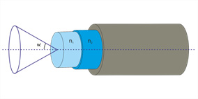
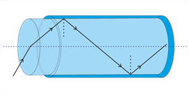
An optical fiber is used to transmit light between the two ends of the fiber. By design, it consists of three layers: core, cladding and buffer. The core is made up of a high refractive index material in contrast to the cladding. Cladding together with the core form a total internal reflection condition thus, the fiber acts as a waveguide transmitting light between two ends of a fiber. The buffer is a protective layer to protect the optical fiber. n1= Core refractive index, n2=Cladding refractive index, n1> n2 is the condition of total internal reflection.
Only a part of light that is incident on the end face of the fiber, within a certain range of angle can be transmitted by an optical fiber. The sine of this angle is called numerical aperture (NA) of the fiber (NA = sinα). The NA indicates the capacity of the fiber to receive the incident light. The greater the NA, the more incident light can be received by the fiber.
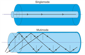
The fiber geometry and composition determine the discrete set of electromagnetic field, which can propagate in the fiber. They are also termed as fiber modes. According to the different transmission modes, optical fiber can be divided in to single-mode fiber and multimode fiber.
The single-mode fiber is made of glass fiber with a diameter of 8.3 to 10 microns and has only one mode of transmission. In contrast to the multimode fiber the single-mode fiber eliminates any distortion by the overlapping of light pulse. Due to the reason of least signal attenuation the single-mode fiber can be used in the communication over a long distance.
The typical multimode fiber has a core diameter 50 to 100 micron. The different frequency components or different mode components of the optical signal transmitted in the optical fiber propagate at different speeds, and after a certain distance the signal will inevitably broaden, therefore it provides high bandwidth over medium distance.
The Bending Loss:
At bends, the light propagation conditions may alter resulting in the loss of light rays in the cladding. The single-mode fiber is more sensitive to the bending loss than the multimode fiber.
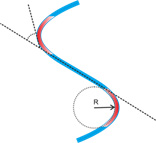
Macrobending Loss:
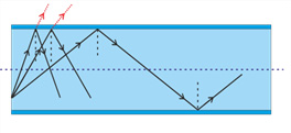
The condition of the total internal reflection will be invalid when the curvature of the bend is much larger than fiber diameter. Thus light tends to enter the cladding resulting in propagation loss. As the radius of the curvature decreases, the loss increases exponentially until it reaches at a certain critical radius. The light propagation will be recovered when the fiber bending is eradicated.
Microbending Loss:
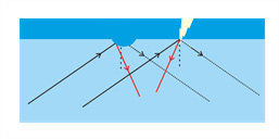
The microscopic bending of the fiber cannot be recovered. Such as small protrusions or depressions on the cladding during production, or mechanical defects due to mechanical or thermal stresses during the installation, so that the light no longer satisfies the total reflection condition and part of the beam is refracted and leak out of the core. There is also power dissipated in this situation. However, fiber manufacturing techniques have been developed quite well and micro bending losses are no longer a major problem. It can be assumed that it is included in the total attenuation given.
Fiber Optic connectors
The Fiber connector realizes the quick connection and disconnection of fiber and equipment. The connector couples and aligns the cores of fibers together. Good connectors achieve very little light loss due to reflection or misalignment of the fibers. We offer a wide range of fiber connectors, such as SMA, Fiber bar, ST and other, more compactor types. The connectors can also be customized according to requirements.